Introduction
Lately I’ve been doing a lot of work with the ARM64 instruction set, and I
thought it would be fun to try to visualize it. ARM64 encodes every instruction
as a 32-bit integer, so one way to visualize the instruction set is by plotting
the instructions along a space-filling curve, such as a Hilbert curve1, and
coloring them according to their instruction class (i.e., general, advsimd,
float, sve, etc…).
Click here for the interactive version.


Generating the visualization
To generate this visualization, I started with Arm’s Machine Readable Architecture (MRA) Specification. The most recent version can be downloaded from here. It comes with both XML and HTML files describing the encoding and semantics of every instruction in the ISA. If you’d like to browse it, I host the HTML files at https://www.scs.stanford.edu/~zyedidia/arm64/. All the visualizations in this blog post were generated from the version released in June 2023, which covers all extensions up to and including ARMv8.9.
I wrote a small tool that parses the XML files and generates a list of all unique encodings in the architecture (roughly 3,000) along with some bits of information like the instruction’s mnemonics, class, what ARMv8 variant/feature it is a part of, and an encoding diagram.
Then I wrote another tool that iterates through every possible 32-bit
instruction, decodes it according to the encoding diagram, and stores its
encoding type in a file. The specification describes bits as combinations of
0, 1, and x, but also sometimes includes (0) and (1). I’m not sure
what the parenthesized versions mean – it seems like some existing
disassemblers treat them as x so that’s what I’ve done. Maybe they are
recommended but not required encodings?
One issue is that while the Arm specification gives encodings as simple
bit-strings, it also provides some code in the Arm Specification Language (ASL)
that can sometimes overrule the encoding. For example, the EOR instruction
encoding becomes undefined if sf == '0' && N != '0'. In the future, I’d like
to parse and process the ASL so that the generated decoder can handle these
cases, but for now I’m handling this by running a post-processing pass that
runs the Capstone disassembler on all the instructions to remove invalid ones,
since Capstone properly understands these rules.
Using this mapping of every possible instruction, we can generate a Hilbert
curve plot with a nice colorscheme, where instructions are categorized based on
their “instruction class”: one of general, system, float, fpsimd,
advsimd, sve, sve2, mortlach, mortlach2, and other. There are too
many instructions to plot each instruction as an individual pixel, so each
pixel in the image corresponds to 256 instructions, and the pixel’s alpha value
corresponds to how filled the pixel is with instructions.
With a nice theme, we get pretty images like these:
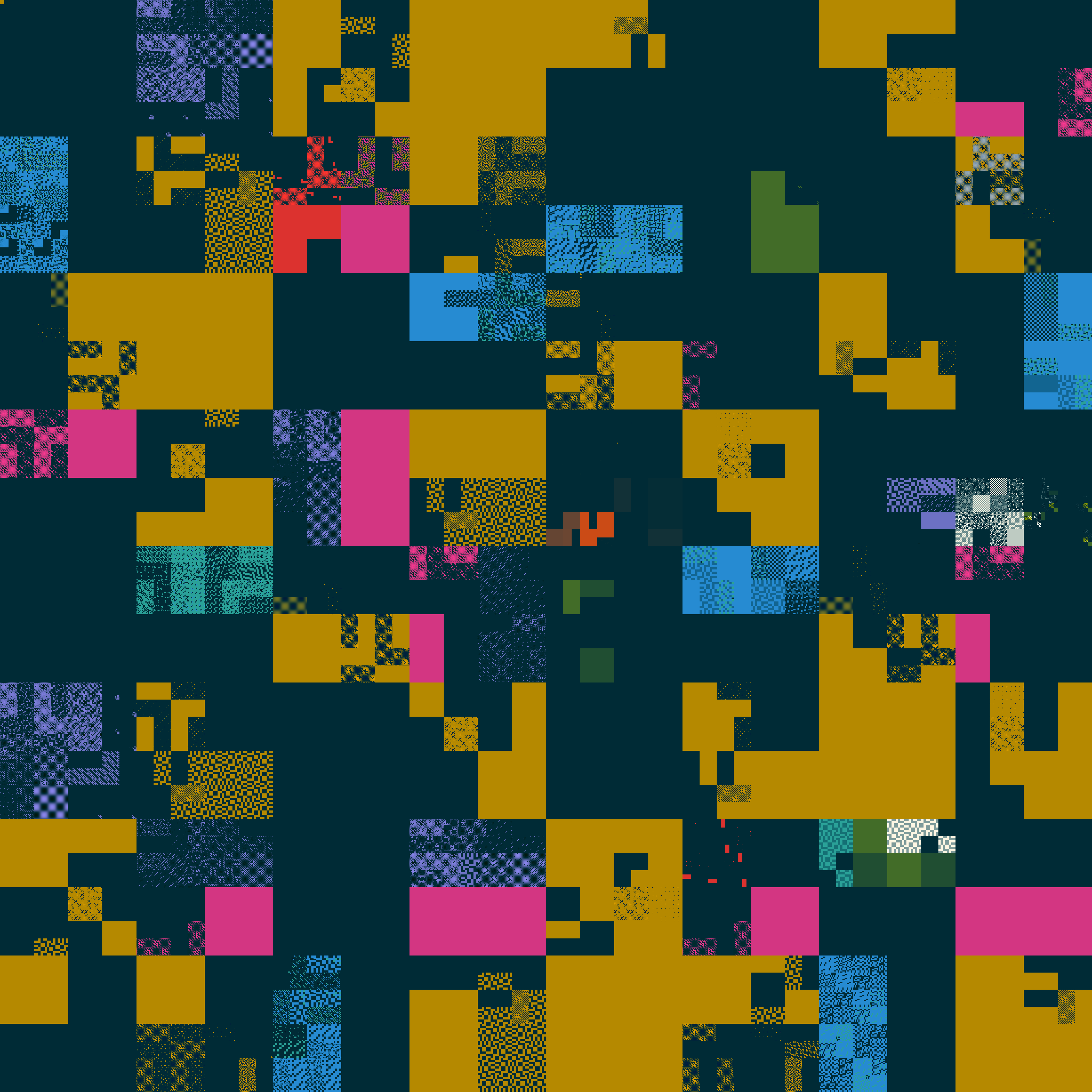
Some of the more interesting patterns are caused by the SVE2 and SME2 (mortlach2)
instructions.
Interactive website
The interactive version is available at https://zyedidia.github.io/arm64/index.html. It lets you inspect the different instructions and choose the overlay that you’d like. The main issue is showing the instruction disassembly as a string. While the Arm specification does have sections for “assembler templates” describing how an instruction should be displayed as a string, the information seems to be intended for a human to read. It’s not immediately easy to consume the format they give and produce a function that simply maps from bits in the instruction to a string representation. I think it is possible, but that will be a project for another time. For now, the web version uses a version of Capstone compiled to WebAssembly to display instruction disassembly. Since it’s a somewhat old version of Capstone, it doesn’t understand all the instructions so in those cases the site just falls back to displaying the name of the instruction.
The interactive version’s fallback also does not take into account the Capstone-based post-processing pass, so it may think some locations have instructions when they in fact do not.
The tools are available at https://github.com/zyedidia/armvis.
Visualizing the LFI verifier
One of my projects that uses ARM64 is called Lightweight Fault Isolation (LFI), and is an efficient software sandboxing approach for ARM64. If you’d like to know the details, you can read the paper, which I’ll be presenting this April at ASPLOS. The code is also available at https://github.com/zyedidia/lfi. I’m also working on a blog post about LFI so stay tuned for that.
LFI uses machine code analysis to determine if a program is safe to run or not. It analyzes an untrusted binary, and only accepts the program to be run inside the sandbox if it can determine that the program will not access memory outside the sandbox or perform other unsafe operations. To make sure this is the case, the verifier only accepts programs consisting of instructions that modify registers and memory according to some invariants. For example, certain registers must always contain addresses within the sandbox’s memory, and these registers may only be modified with instructions that guarantee that this invariant is maintained. The paper gives more details about how this is actually possible, and how this can be used to make a secure sandbox.
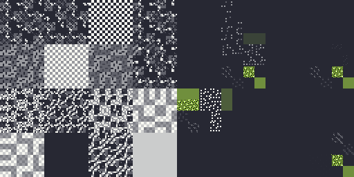
In fact, it is possible to design a verifier that only looks at one instruction at a time to determine if the overall program is legal or not (although the current LFI verifier does not work this way – it has some lookahead to allow for more optimizations). Some of my current research is about the consequences of designing a verifier this way (with some exciting in-progress results). In any case, this also means it’s possible to visualize the verifier by displaying all the legal instructions with a Hilbert curve heatmap (see here for the IPv4 version that this kind of visualization is based on). Again, every pixel is 256 instructions, but this time it’s a heatmap, meaning that blue indicates that the pixel does not have many legal instructions, and red indicates that the pixel is full of legal instructions.
On top of the verifier’s restrictions due to security, the initial version of LFI also only supports ARMv8.0, so the picture shown below looks a lot sparser than the full ARMv8.9 instruction set from earlier. In the future I’d like to add support for more extensions, since the vast majority of additional instructions don’t pose any problems for LFI.
Only about 750M instructions are legal with this verifier, and there are many
partial regions. This is due to LFI enforcing invariants on certain
registers, which heavily limits how those registers can be modified. As a
result, many instructions on particular registers (x18, x21, x22,
x23, x24, sp) are disallowed. The verifier also restricts the types of
addressing modes that can be used, and what registers they can be used with.
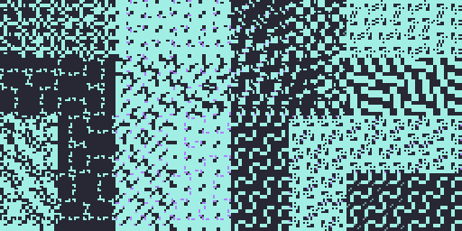
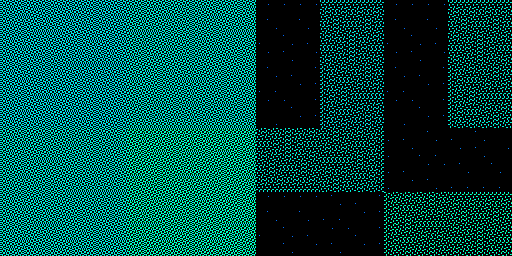
For example, the checkered blue areas are typically blocks of load/store
instructions. The picture below shows the encoding space for ldrh/strh and
related instructions. The area on the left consists of instructions with a
register-immediate addressing mode. Each blue pixel is a block of instructions
containing accesses that use x18, x23, x24, x30, or sp, which are all
legal. In the sparse area on the right, the encodings use register-register
addressing modes, of which many fewer are safe. The few dark blue dots are
because of the [x21, wX, uxtw] addressing mode, which is the one
configuration of the register-register addressing mode that is safe.
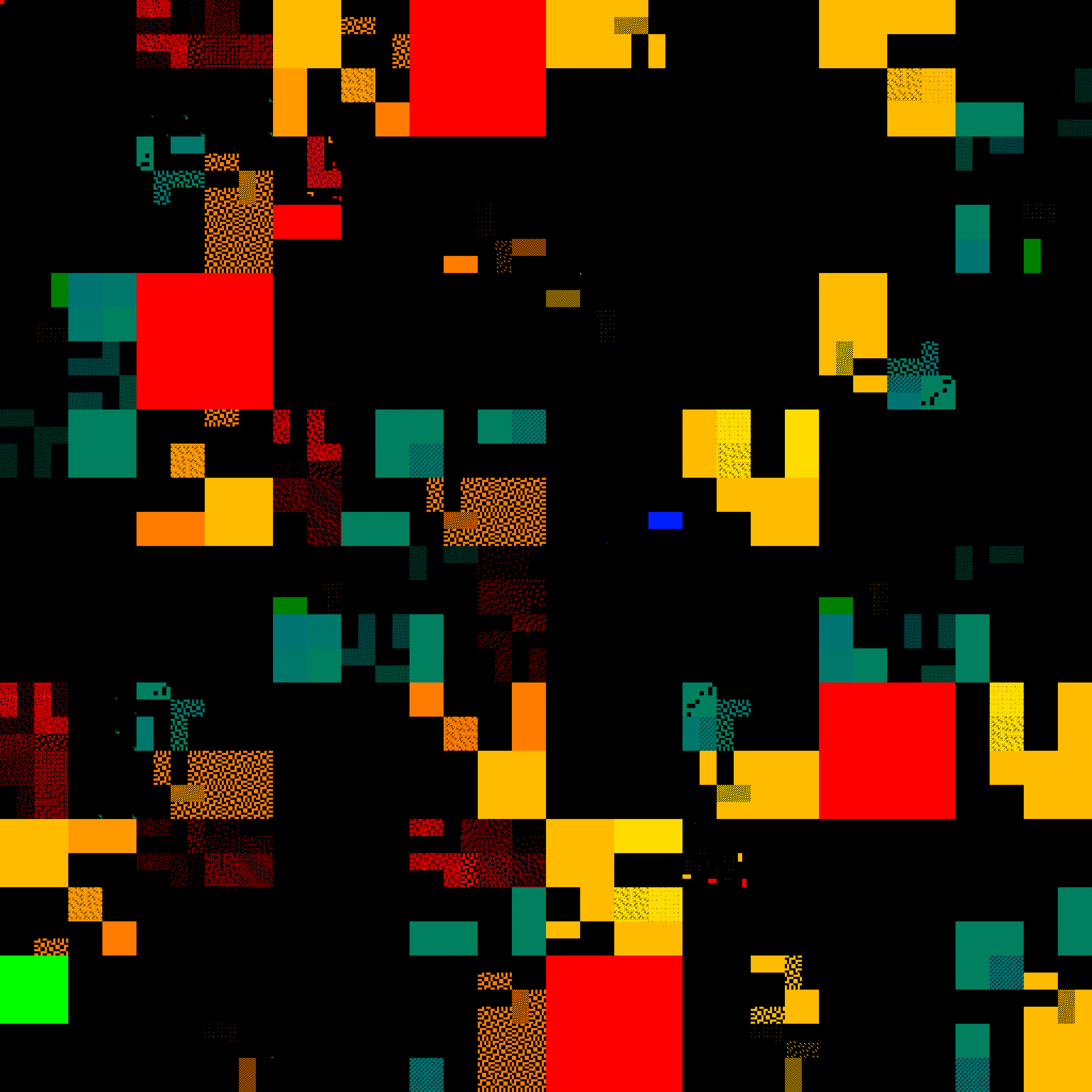
You can generally find all the load/store instructions by looking for the checkered light blue regions. The yellow regions are generally ALU operations, which mostly consist of legal instructions except for the instructions that modify reserved registers. The full red regions are generally the direct branches, which are always guaranteed to be legal thanks to static branch range being limited to less than the size of a sandbox. SIMD and floating point instructions are also usually red because they don’t access memory or modify reserved registers. Not only does it generate a cool picture, but the visualization can help sanity-check the correctness of the verifier.
Conclusion
Thanks for reading! Generating these images has been a fun distraction for me. It would be cool to make a similar visualization for RISC-V and compare it with ARM64. Maybe next time. I’m also investigating methods for auto-generating disassemblers that are much more efficient than existing ones, so I might have an update if that works out.
-
This approach is inspired from the XKCD showing this for the IPv4 address space: https://xkcd.com/195/. ↩︎